
|
|
||
|
|
||
|
For whatever reason, Nintendo opted to remove the RGB output from their
N64. As near as I can tell it was a matter of a few traces from a
chip (U4) to the AV output, but that's their business. According
to 64 DREAM magazine, Nintendo knew RGB was the least popular method of
connecting a SNES, so they didn't bother with the N64.
C'est la vie. These instructions were apparently written by
someone named RYU. I have installed this mod and had great success with
it. The picture is clear, if a little weak. As usual, the
caveats apply.
Opening the Nintendo 64 is difficult and requires special tools,
see here.
Note! This mod does not work on PAL N64 units! We are trying to find out why, but so far no luck. Perform the mod at your own risk, and if you manage to find the right method for RGB output on a PAL N64, please let us know! |
||
![[Pic of chip U4]](../grafx/n64u4.gif)
|
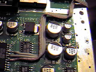
Many times, people are complaining about the weak
N64 RGB signals. As I have never had this problem, and my N64 RGB mod is
different from the 'standard' RGB mod circulating around the net, I decided
to make a gif.
What I believe is responsible for the good quality RGB I get is the fact that the RGB signals are tapped directly from the chip itself and not from the (signal-weakening) resistors C124, C125 and C126 on the downside of the board. I have a Jap N64 by the way, but since all N64 boards are identical apart from the lockout on the PAL version, this method will almost certainly work. Of course, I take no responsibility for any damage the procedure might cause. -Ryu |
|
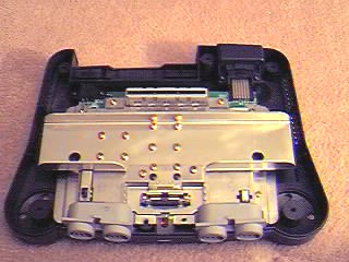 Nice massive heat sink, eh? 1 - remove the two bits of shielding near the jumper-pak port. Pay attention to which screws come from where. 2 - remove the heat sink, and place it to the side. |
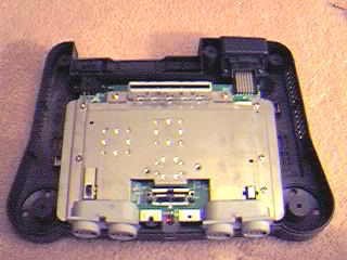 3 - remove the RF shielding next - 5 screws along the side hold it down. | |
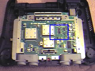 4 - locate the U4 VDC chip. |
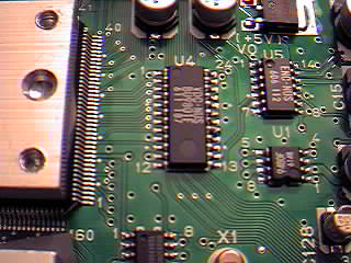 5 - identify pins 17, 19 and 21. Pin 13 is labelled for your convenience. |
|
 6 - attach three wires, and string them out approximately as shown. You will have to bend the RF shield at the point where the wires go out from under it. |
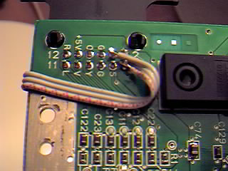 7 - Attach the three wires as shown in the above schematic. Re-assemble the N64 making sure to replace the Jumper Pak! |
|
|
All contents (c)1999 Game Station X unless otherwise noted. All trademarks copyright of their respective companies. Game Station X assumes absolutely no responsiblility whatsoever for any sort of damages incurred while either viewing this information or doing anything with said information. If you don't like it, change the channel. Some of this information may have come from other sources, and Game Station X in no way implies ownership of this information, and merely intends to provide a convenient source for finding this information. That said, we wrote this, and would appreciate your not lifting it for your own page without due credit. Mail us! |